37+ one to one relationship in er diagram
2 ER diagram in dbms stands for entity relationship which helps us to understand the. A one-to-one relationship is a type of relationship in ER diagram that assigns one entity to another entity.
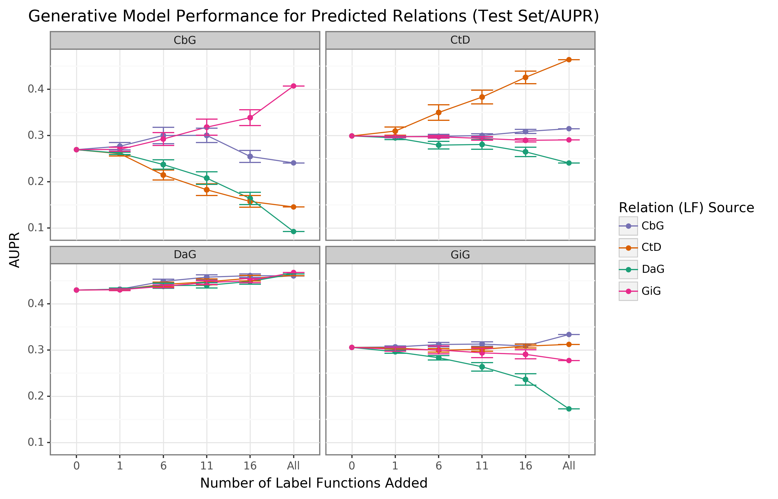
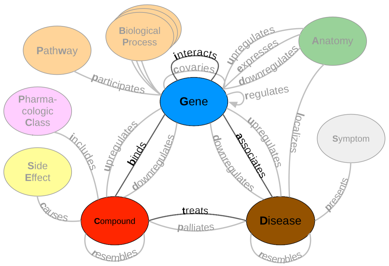
Expanding A Database Derived Biomedical Knowledge Graph Via Multi Relation Extraction From Biomedical Abstracts
Person and events are two different entity.
. Now lets review some examples of real-world one-to-many-relationships. Relationships are usually verbs such as. Here Only one table is required.
There are three basic elements in an ER Diagram. ER Model in DBMS stands for an Entity-Relationship model. On the toolbar click the.
In the above ER-Diagram we have only one One-to-One. It is the relationship between the instances of two different entity types. Eer diagram in dbms reducing er diagrams.
There are more elements which are based on the main elements. The number of times an entity of an entity set participates in a relationship set is known as cardinality. The complete ER-Diagram is as shown below.
How to create a new one to many relationship Add two tables to the ER diagram. Some Practical Examples of 1N Relationships. An entity-relationship ER diagram can be created based on these three types which are listed below.
Cardinality can be of different types. Any object such as entities attributes of an entity sets of relationship. One-to-Many Relationship Using Primary Keys.
ERD relationship symbols Within entity-relationship diagrams relationships are used to document the interaction between two entities. ER diagrams are a visual tool which is helpful to. Two entities will participate in the relationship.
Up to 24 cash back An ER diagram or Entity Relationship Diagram ERD is a type of flowchart or graphical approach that helps you illustrate how different entities relate to each. One-to-One Relationships in ER Diagram to Database Schema. A foreign key attribute references one or zero instances of the.
One to one. The ER model is a high-level data model diagram. They are weak entity multi.
ER-Diagram is a pictorial representation of data that describes how data is communicated and related to each other. Then create a new relationship. There are three types of relationships that can exist between two entities.
Expanding A Database Derived Biomedical Knowledge Graph Via Multi Relation Extraction From Biomedical Abstracts

Should Neonates Sleep Alone Biological Psychiatry

Chen Style Cardinality Erd Relationship Diagram Diagram Relationship

Martin Style Cardinality Erd Relationship Diagram Diagram Relationship

Er Diagram For One To Many Relationship Relationship Diagram Diagram Relationship
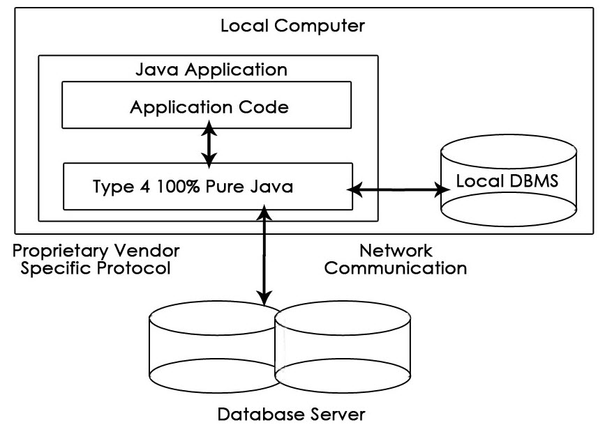
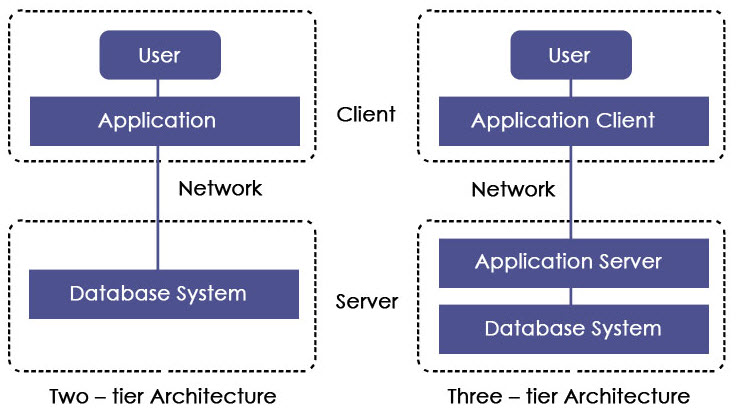
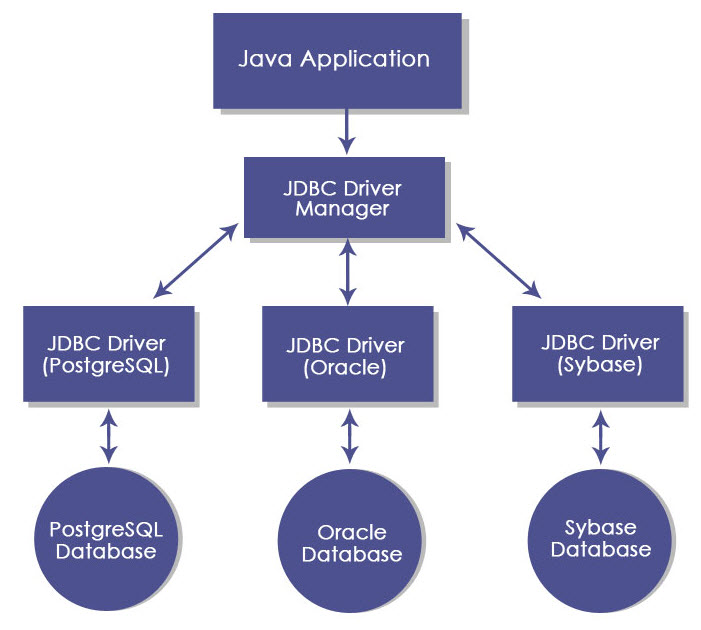
Jdbc Architecture Interfaces Types Components Architecture
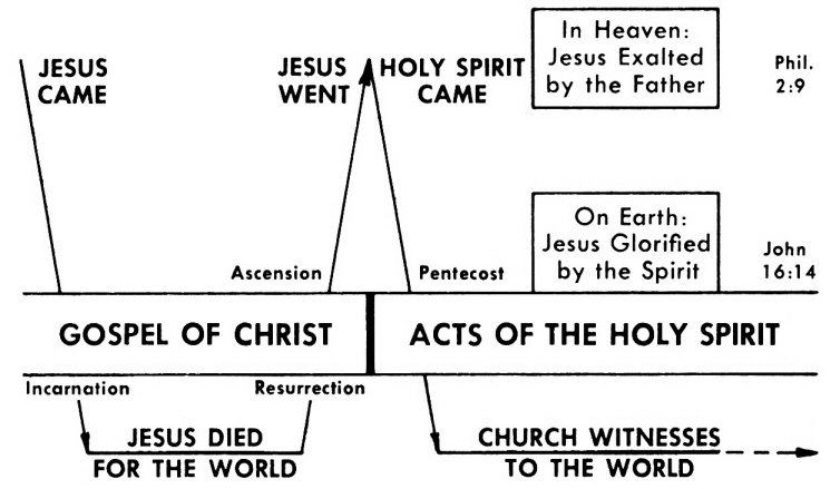
Acts 13 Commentary Precept Austin

Example Image Internet Sales Entity Relationship Diagram Relationship Diagram Diagram Relationship

Information Engineering Style Cardinality Erd Relationship Diagram Information Engineering Diagram

Entity Relationship Diagram Common Erd Symbols And Notations Relationship Diagram Diagram Erd
Jdbc Architecture Interfaces Types Components Architecture
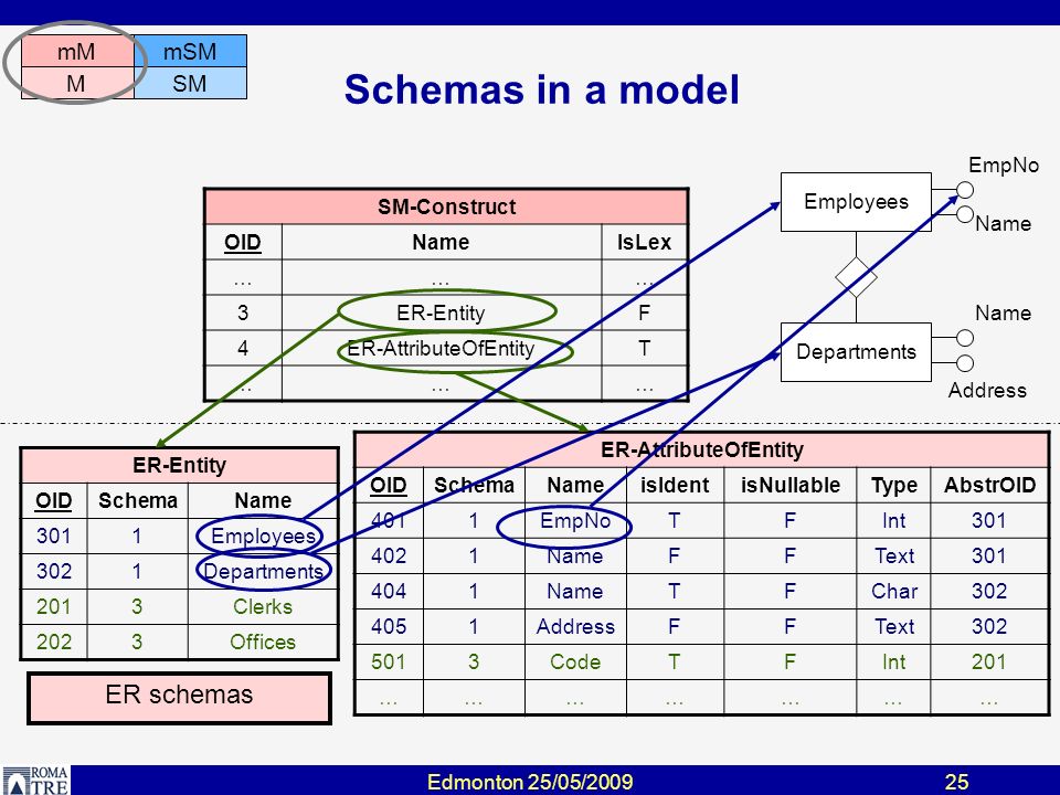
Model Independent Schema And Data Translation A Run Time Approach Paolo Atzeni Based On Work Done With L Bellomarini P Bernstein F Bugiotti P Cappellari Ppt Download
2
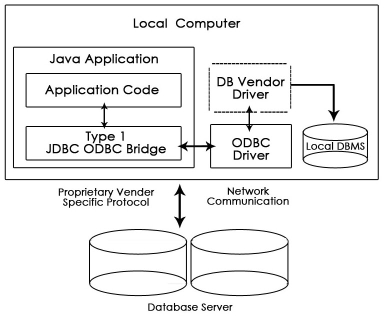
Jdbc Architecture Interfaces Types Components Architecture
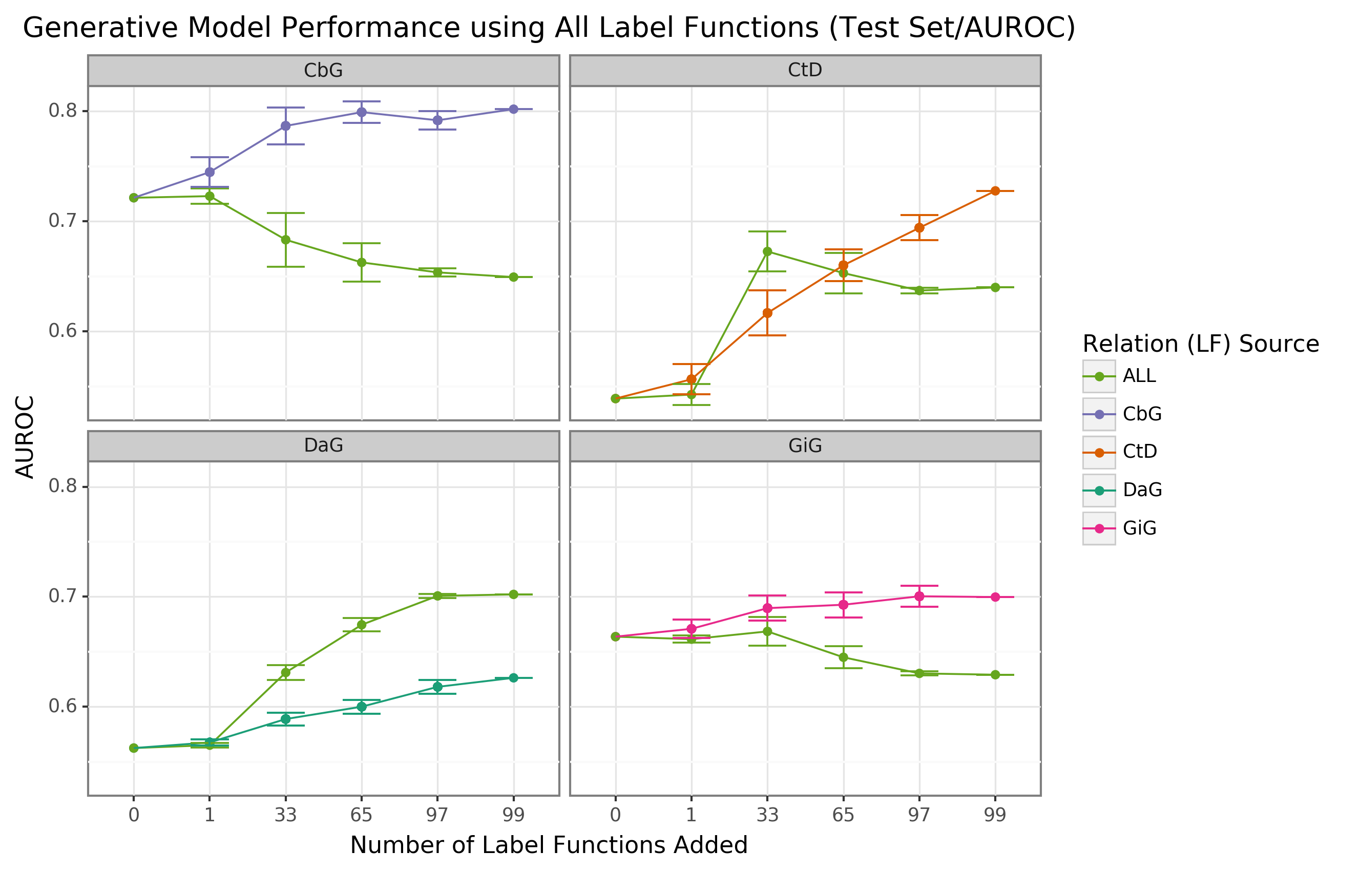
Expanding A Database Derived Biomedical Knowledge Graph Via Multi Relation Extraction From Biomedical Abstracts
Jdbc Architecture Interfaces Types Components Architecture

Model Independent Schema And Data Translation A Run Time Approach Paolo Atzeni Based On Work Done With L Bellomarini P Bernstein F Bugiotti P Cappellari Ppt Download